Types Of Cable
a. Twisted Pair

Twisted pair is the ordinary copper wire that connects home and many business computers to the telephone company. To reduce crosstalk or electromagnetic induction between pairs of wires, two insulated copper wires are twisted around each other. Each connection on twisted pair requires both wires. Since some telephone sets or desktop locations require multiple connections, twisted pair is sometimes installed in two or more pairs, all within a single cable. For some business locations, twisted pair is enclosed in a shield that functions as a ground. This is known as shielded twisted pair (STP). Ordinary wire to the home is unshielded twisted pair (UTP).

Twisted pair is now frequently installed with two pairs to the home, with the extra pair making it possible for you to add another line (perhaps for modem use) when you need it.
Twisted pair comes with each pair uniquely color coded when it is packaged in multiple pairs. Different uses such as analog, digital, and Ethernet require different pair multiples.
Although twisted pair is often associated with home use, a higher grade of twisted pair is often used for horizontal wiring in LAN installations because it is less expensive than coaxial cable.
Two Kinds of Twisted Pair
a. STP "Shielded Twisted Pair"

Shielded twisted pair (STP) cable was originally designed by IBM for token ring networks that include two individual wires covered with a foil shielding, which prevents electromagnetic interference, thereby transporting data faster.
STP is similar to unshielded twisted pair (UTP); however, it contains an extra foil wrapping or copper braid jacket to help shield the cable signals from interference. STP cables are costlier when compared to UTP, but has the advantage of being capable of supporting higher transmission rates across longer distances.

The other usual STP cables, often called foil twisted-pair cables or screened twisted-pair cables, make use of just a thinner outer foil shield. These cables are thin and more affordable versus the braided STP cable; but they are very difficult to install. Except in cases where the maximum pulling tension and minimum bend radius are strictly observed, these thinner cables may be torn during the installation process.
Furthermore, STP cables have some other drawbacks. STP cables function by drawing external interference to the shield, then getting rid of it into a grounded cable. If the ground cable is not properly grounded, STP's noise-canceling functionality can be seriously compromised.
b. UTP "Unshielded Twisted Pair"

UTP stands for Unshielded Twisted Pair cable. UTP cable is a 100 ohm copper cable that consists of 2 to 1800 unshielded twisted pairs surrounded by an outer jacket. They have no metallic shield. This makes the cable small in diameter but unprotected against electrical interference. The twist helps to improve its immunity to electrical noise and EMI.

UTP cables are mostly used for LAN networks. They can be used for voice, low-speed data, high-speed data, audio and paging systems, and building automation and control systems. UTP cable can be used in both the horizontal and backbone cabling subsystems.
Horizontal UTP cable is four-pair construction by industry cabling standard. Each pair has two conductors. One wire of the pair is assigned the pair color with a white stripe and the other wire is assigned the color white with the pair color stripe. The table below lists the pair and color code for a four-pair horizontal UTP cable.
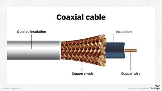
b. Coaxial Cable
A coaxial cable is a type of shielded and insulated copper cable that is used in computer networks and to deliver cable TV services to end users. It was first commercially implemented in the early 1940s and is used for both baseband and broadband data communication services.
Coaxial cable is also known as coax, which is derived from the geometric axis created between a shield and insulator.

A coaxial cable is used by cable TV service providers to stretch transmission lines from their branch or control offices to residential and business subscribers.
-It consists of four primary components, as follows:
-A core copper wire, which serves as the primary channel
-A dielectric plastic insulator, which surrounds the copper
-A braided copper/aluminum sheath beneath the insulator. This is used to protect from external electromagnetic interference.
-The last layer, which is made of Teflon or plastic coating, is used to protect the inner layers from physical damage, such as fire and water.

Coaxial cables tend to carry signals at a greater distance and are a good choice for weak signals, due to their layered protection. There are several types of coaxial cables, which are classified by the inner copper core diameter and number of protective sheaths.
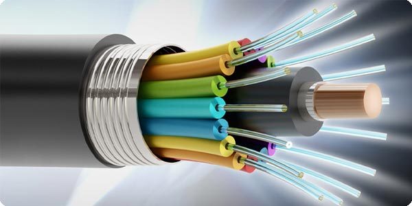
c. Fiber Optic
A fiber optic cable is a network cable that contains strands of glass fibers inside an insulated casing. They're designed for long distance, very high-performance data networking, and telecommunications.
Compared to wired cables, fiber optic cables provide higher bandwidth and can transmit data over longer distances. Fiber optic cables support much of the world's internet, cable television, and telephone systems.
Fiber optic cables carry communication signals using pulses of light generated by small lasers or light-emitting diodes (LEDs).
The cable consists of one or more strands of glass, each only slightly thicker than a human hair. The center of each strand is called the core, which provides the pathway for light to travel. The core is surrounded by a layer of glass called cladding that reflects light inward to avoid loss of signal and allow the light to pass through bends in the cable.

The two primary types of fiber cables are called single mode and multi-mode fiber. Single mode fiber uses very thin glass strands and a laser to generate light while multi-mode fibers use LEDs.
Single mode fiber networks often use Wave Division Multiplexing (WDM) techniques to increase the amount of data traffic that can be sent across the strand. WDM allows light at multiple different wavelengths to be combined (multiplexed) and later separated (de-multiplexed), effectively transmitting multiple communication streams via a single light pulse.
The Difference Between Straight-through Cable
and Cross-over Cable
Ethernet cables can be wired as straight through or crossover. The straight through is the most common type and is used to connect computers to hubs or switches. They are most likely what you will find when you go to your local computer store and buy a patch cable. Crossover cable is more commonly used to connect a computer to a computer and may be a little harder to find since they aren’t used nearly as much as straight through cable. Then, what’s the difference between them? Difference between straight through and crossover cables will be introduced in this blog.
T568A And T568B Wiring Standard Basis
A RJ45 connector is a modular 8 position, 8 pin connector used for terminating Cat5e or Cat6 twisted pair cable. A pinout is a specific arrangement of wires that dictate how the connector is terminated. There are two standards recognized by ANSI, TIA and EIA for wiring Ethernet cables. The first is the T568A wiring standard and the second is T568B. T568B has surpassed 568A and is seen as the default wiring scheme for twisted pair structured cabling. If you are unsure of which to use, choose 568B.
 What Is Straight Through Cable?
A straight through cable is a type of twisted pair cable that is used in local area networks to connect a computer to a network hub such as a router. This type of cable is also sometimes called a patch cable and is an alternative to wireless connections where one or more computers access a router through a wireless signal. On a straight through cable, the wired pins match. Straight through cable use one wiring standard: both ends use T568A wiring standard or both ends use T568B wiring standard. The following figure shows a straight through cable of which both ends are wired as the T568B standard.
What Is Crossover Cable?
An Ethernet crossover cable is a type of Ethernet cable used to connect computing devices together directly. Unlike straight through cable, crossover cables use two different wiring standards: one end uses the T568A wiring standard, and the other end uses the T568B wiring standard. The internal wiring of Ethernet crossover cables reverses the transmit and receive signals. It is most often used to connect two devices of the same type: e.g. two computers (via network interface controller) or two switches to each other.
 Choose a Straight Through or Crossover Cable?
Usually, straight through cables are primarily used for connecting unlike devices. And crossover cables are use for connecting unlike devices alike devices.
Use straight through cable for the following cabling:
-Switch to router
-Switch to PC or server
-Hub to PC or server
Use crossover cables for the following cabling:
-Switch to switch
-Switch to hub
-Hub to hub
-Router to router
-Router Ethernet port to PC NIC
-PC to PC
 Conclusion
Straight through and crossover cables are wired differently from each other. One easy way to tell what you have is to look at the order of the colored wires inside the RJ45 connector. If the order of the wires is the same on both ends, then you have a straight through cable. If not, then it’s most likely a crossover cable or was wired wrong. At present, the straight through cable is much more popular than crossover cable and is widely used by people. FS.COM provides a full range straight through Cat5e, Cat6, Cat6a and Cat7 Ethernet patch cables with many lengths and colors options.


![Image result for type ping [IP address]](https://lh3.googleusercontent.com/blogger_img_proxy/AEn0k_s8lbqnwyTcUSmII3I4WWKPmyPY97-wFHcmxhFYQIiMvPig_x-6KGOMv--p9RMBwuKXN0T9c10mX0enCd-QILaZ1vkqqbtlQL-EccbV0ctICdv3ejTDB8V_x4Dv2J0x=s0-d)